BSE_Template_Portfolio
A template repository for students to use
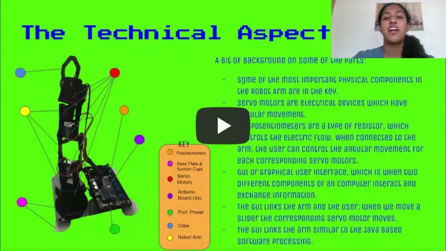
Phone Controlled Robot Arm
In Iron Man 3, we see Avenger Tony Stark work with a robot arm to perform and create new pieces of the Ironman suit. Although it may not be as advanced as Ironman’s arm, the Phone Controlled Robot Arm is unique in it’s own way. Through combining various aspects of mechanical,software, and electrical engineering the user can control the arm through three different modifications which include Potentiometer(s), a GUI, and Processing.
| Engineer | School | Area of Interest | Grade |
|---|---|---|---|
| Meghana K. | Amador Valley HighSchool | Mechanical, Computer Science, and Aerospace Engineering | Incoming Junior |
About the Creator
Hello, I’m Meghana, and here is my portfolio, of my project I created in 3 weeks. After a lot of time, occasional tears, and effort, I’ve been able to create an amazing website and demo. Please Enjoy!

The Project
Here is the project with the various modifications!

Presentation
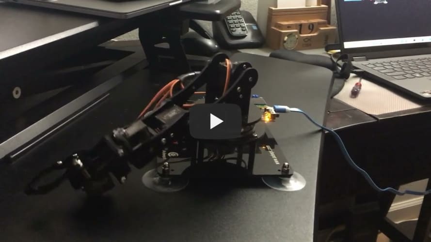
Project Demo
Here is the clip from Demo night to showcase and summarize my entire project.

Final Milestone
My final milestone was to try connecting the Arm through the java app; Processing. I downlaoded Processing and was able to open the software properly on my laptop, it worked very well and I could see the interface. I did not have as much trouble as I did with the GUI interface. I was able to upload the code, but certain errors kept popping up. I had to reconnect my ports several times in order for it to work properly. There was also some occasional lag with the arm and the itnerface, possibly due to hardware issues or wifi. I decided to play around with the Processing part. I tried to control the Robot Arm picking up a Pom-Pom and moving it around. it ook some tries but I could finally achieve it and in doing so was able to move it around a bit. I then workd on my Demo night and presentation where I created a slideshow to showcase all my work and experince from three weeks. It was a success!
Second Milestone
My second milestone was by far the most difficult milestone, I had to build the robot, add two modifications: Potentiometers and the GUI(Graphical User Interface). Building the robot arm took almost 1.5 days for be to finish; it was quick and fast. Except for the occasional bolts and missing screws I’d have to find and put back together. When working, I checked to see if every motor was working and had a range of motion, so I could in replace the servo if something were to happen. This way it worked well and I wouldn’t have to take apart any of the motors if there was an issue later on. Next I had to try with the first modification which was with the potentiometers. The Arduino Uno board had built in Potentiometers that I used to control the robot arm. Within the first try everything worked pretty well for me. The potentiometers could control how the arm was used. The Servo Motor two had some issue because it had to uphold the entire weight of the arm; it would move but not to the full possible extension. I uploaded code from the Arduino IDE program to the board and checked to see if all my ports were place correctly. It worked pretty well. Next I did the GUI or Graphical User Interface. I had the most issues and difficulties with this step. The Interface would not work, so I had to redownload all the programs in several different laptops and devices before it finally worked on another device. It then successfully worked. I believe my laptop had some issues with other programs and an Antivirus protection that’s why there was so many issues. After a long and tedious process I was finally able to solve the challenge.
First Milestone
My first milestone was being able to connect a servo motor and control it through an APK app on my device. At first this was a tad bit difficult as I had not previously used Android devices; it was a different medium for me. I was able to use an Andorid tablet to process and dowload this app. Utilizing the HC-05 Bluetooth module, I was able to connect the servo motor through bluetooth, meaning that I could control the servo motor wirelessly. I first connected and fastened the wires to the breadboard and the arduino board. the arduino board was attached to my latop via a cable. This allowed the transfer of power originally from my laptop to my arudino board. (It was a main source of power). By using the APK I was able to control my servo motor and allow to undergo a rotation of about 180 degrees. What I tended to notice towards the end was that, the robot arm could only handle moving to a certain number of degrees withint the 180. It would occasionally move from 45-80 , or 35-80. So I had to put together the entire component for it to work again. But in the end it worked well.
Bill Of Materials
| Item | Qty | Price | Where to Buy |
|---|---|---|---|
| Adeept Robotic Arm Kit | 1 | $64.99 | https://www.amazon.com/dp/B087R8DLG6 |
| Breadboard | 1 | $6.75 | https://www.amazon.com/BB400-Solderless-Plug-BreadBoard-tie-points/dp/B0040Z1ERO |
| Potentiometer | 1 | $1.85 | https://www.tubesandmore.com/products/potentiometer-alpha-linear-38-bushing |
| Micro Servo | 1 | $5.95 | https://www.adafruit.com/product/169 |
| Jumper Wires | 6 | 10¢/wire | https://www.amazon.com/Breadboard-Jumper-Wire-75pcs-pack/dp/B0040DEI9M |
| Arduino Uno Board | 1 | $27.60 | https://store-usa.arduino.cc/products/arduino-uno-rev3?selectedStore=us |
| Arduino IDE | 1 | $0 | https://www.arduino.cc/en/software/ |
Final Milestone: An Schematic To Connect To The Bluetooth Module.

The Diagram For Milestone 1

Getting Used to Arduino: Potentiometer, and LED(s)


Code
Here is some of the code I used to control and change my modifications for my Robot Arm!
#include <Servo.h>
int servopin1 = 9;    //Define servo interface digital interface 9
int servopin2 = 6;    //Define servo interface digital interface 6
int servopin3 = 5;    //Define servo interface digital interface 5
int servopin4 = 3;    //Define servo interface digital interface 3
int servopin5 = 11;   //Define servo interface digital interface 11

int moveServoData;
int servo1Angle=90;
int servo2Angle=90;
int servo3Angle=90;
int servo4Angle=90;
int servo5Angle=90;
Servo servo1;
Servo servo2;
Servo servo3;
Servo servo4;
Servo servo5;
int angle = 90;        //Angle of rotation of the servo

boolean autoLock = false;
//boolean key_mouse_lock = false;
boolean closeLock = false;

void setup() {
  // put your setup code here, to run once:
  pinMode(servopin1,OUTPUT);//Set the servo interface as the output interface
  pinMode(servopin2,OUTPUT);//Set the servo interface as the output interface
  pinMode(servopin3,OUTPUT);//Set the servo interface as the output interface
  pinMode(servopin4,OUTPUT);//Set the servo interface as the output interface
  pinMode(servopin5,OUTPUT);//Set the servo interface as the output interface
  Serial.begin(9600);
  servo1.attach(servopin1);
  servo2.attach(servopin2);
  servo3.attach(servopin3);
  servo4.attach(servopin4);
  servo5.attach(servopin5);
  servo1.write(90);
  servo2.write(90);
  servo3.write(90);
  servo4.write(90);
  servo5.write(90);
  delay(20);
  //servo1Pulse(90);
}
void loop() {
  delay(20);
  do{
    moveServoData = Serial.read();
    if (moveServoData == 111) {//o
      autoLock = false;
      closeLock=false;
      servo1Angle++;
      if(servo1Angle>=180){servo1Angle=180;}
      servo1.write(servo1Angle);
    }
    if (moveServoData == 112){//p
      autoLock = false;
      closeLock=false;
      servo1Angle--;
      if(servo1Angle<=0){servo1Angle=0;}
      servo1.write(servo1Angle);
    }
    if (moveServoData == 117) {//u
      autoLock = false;
      closeLock=false;
      servo2Angle++;
      if(servo2Angle>=180){servo2Angle=180;}
      servo2.write(servo2Angle);
    }
    if (moveServoData == 105) {//i
      autoLock = false;
      closeLock=false;
      servo2Angle--;
      if(servo2Angle<=0){servo2Angle=0;}
      servo2.write(servo2Angle);
    }
    if (moveServoData == 116) {//t
      autoLock = false;
      closeLock=false;
      servo3Angle++;
      if(servo3Angle>=180){servo3Angle=180;}
      servo3.write(servo3Angle);
    }
    if (moveServoData == 121) {//y
      autoLock = false;
      closeLock=false;
      servo3Angle--;
      if(servo3Angle<=0){servo3Angle=0;}
      servo3.write(servo3Angle);
    }


    if (moveServoData == 101) {//e
      autoLock = false;
      closeLock=false;
      servo4Angle++;
      if(servo4Angle>=180){servo4Angle=180;}
      servo4.write(servo4Angle);
    }
    if (moveServoData == 114) {//r
      autoLock = false;
      closeLock=false;
      servo4Angle--;
      if(servo4Angle<=0){servo4Angle=0;}
      servo4.write(servo4Angle);
    }
    if(moveServoData == 113) {//q
      autoLock = false;
      closeLock=false;
      servo5Angle++;
      if(servo5Angle>=90){servo5Angle=90;}
      servo5.write(servo5Angle);
    }
    if(moveServoData == 119) {//w
      autoLock = false;
      closeLock=false;
      servo5Angle--;
      if(servo5Angle<=35){servo5Angle=35;}
      servo5.write(servo5Angle);
    }
    if(moveServoData == 110){//n
      autoLock = true;
//      key_mouse_lock = false;
      closeLock=false;
    }
  }
  while(Serial.available()>0);

}
Here’s some code for the Potentiometer Modification!
#include <Servo.h>
Servo servo1;//create servo object to control a servo
Servo servo2;//create servo object to control a servo
Servo servo3;//create servo object to control a servo
Servo servo4;//create servo object to control a servo
Servo servo5;//create servo object to control a servo
//The following can be modified according to your specific needs
int dataServo1 = 90; // Servo 1 rotation range(dataServo1=0~180)
int dataServo2 = 90; // Servo 2 rotation range(dataServo2=0~180)
int dataServo3 = 90; // Servo 3 rotation range(dataServo3=0~180)
int dataServo4 = 90; // Servo 4 rotation range(dataServo4=0~180)
int dataServo5 = 90; // Servo 5 rotation range(dataServo5=35~90)

char val;
int incomingByte = 0;          // Received data byte
String inputString = "";         // Used to store received content
boolean newLineReceived = false; //  Previous data end flag
boolean startBit  = false;  //Acceptance Agreement Start Sign
int num_reveice=0;

float dirServo1Offset = 0;    // define a variable for deviation(degree) of the servo
float dirServo2Offset = 0;    // define a variable for deviation(degree) of the servo
float dirServo3Offset = 0;    // define a variable for deviation(degree) of the servo
float dirServo4Offset = 0;    // define a variable for deviation(degree) of the servo
float dirServo5Offset = 0;    // define a variable for deviation(degree) of the servo
int val1;
int val2;
int val3;
int val4;
int val5;
void setup()
{
  servo1.attach(9);//attachs the servo1 on pin 9 to servo object
  servo2.attach(6);//attachs the servo2 on pin 6 to servo object
  servo3.attach(5);//attachs the servo3 on pin 5 to servo object
  servo4.attach(3);//attachs the servo4 on pin 3 to servo object
  servo5.attach(11);//attachs the servo5 on pin 11 to servo object

  servo1.write(dataServo1+dirServo1Offset);//goes to dataServo1 degrees
  servo2.write(dataServo2+dirServo2Offset);//goes to dataServo2 degrees
  servo3.write(dataServo3+dirServo3Offset);//goes to dataServo3 degrees
  servo4.write(dataServo4+dirServo4Offset);//goes to dataServo4 degrees
  servo5.write(dataServo5+dirServo5Offset);//goes to dataServo5 degrees

  Serial.begin(9600); //  set the baud rate to 9600
}
void loop()
{
 while (Serial.available())
  {
    incomingByte = Serial.read();              //One byte by byte, the next sentence is read into a string array to form a completed packet
    if (incomingByte == '%')
    {
      num_reveice = 0;
      startBit = true;
    }
    if (startBit == true)
    {
      num_reveice++;
      inputString += (char) incomingByte;
    }
    if (startBit == true && incomingByte == '#')
    {
      newLineReceived = true;
      startBit = false;
    }
    if(num_reveice >= 20)
    {
      num_reveice = 0;
      startBit = false;
      newLineReceived = false;
      inputString = "";
    }
  }
  if(newLineReceived)
  {
      Serial.println(inputString);
  }
  servo1.write(dataServo1+dirServo1Offset);//goes to dataServo1 degrees
  servo2.write(dataServo2+dirServo2Offset);//goes to dataServo2 degrees
  servo3.write(dataServo3+dirServo3Offset);//goes to dataServo3 degrees
  servo4.write(dataServo4+dirServo4Offset);//goes to dataServo4 degrees
  servo5.write(dataServo5+dirServo5Offset);//goes to dataServo5 degrees

  val1 = map(analogRead(0), 0, 1023, 0, 180);
  val2 = map(analogRead(1), 0, 1023, 0, 180);
  val3 = map(analogRead(2), 0, 1023, 0, 180);
  val4 = map(analogRead(3), 0, 1023, 0, 180);
  val5 = map(analogRead(6), 0, 1023, 35, 90);

  dataServo1 = val1;
  dataServo2 = val2;
  dataServo3 = val3;
  dataServo4 = val4;
  dataServo5 = val5;
  delay(50);//wait for 0.05second
}
Blast From The Past: Time to Recreate The Project
When recreating the project, know that it is not too difficult of a task, but neither is it too easy. Grab a screwdriver or two, and have a positive and open mindset througout the building process to have the most success. Not to mention have fun! If you face issues regarding servo motors, take apart the corresponding servo motor from the diagram and replace or attempt to screw it back together. Keep a pair of pliers or wrenches to help you fix the pesky screws and bolts. Do not use pressure or handle the robot arm with roughness. The components may definitely break! Do not apply too much pressure. If your program is not working either restart the laptop or computer you are using, or re-upload the code. Make sure all your ports are connected check the “Tools” button in Arduino. Be careful at all time and have fun again! *** I also suggest looking here and following the instructions: http://www.adeept.com/learn/details/id/31.
Caution
If you sense something is wrong or a certain acid is leaking from any components immediately stop what you are doing and wear protective wear. Dispose of the component and clean the surface area properly. If a servo motor starts to heaten up, take not carefully. Please turn of the power or pwoer source (in this case it will most likely be your laptop), unplug the cable, and let the motor reach back down to temperature. Certain times you may feel a burning heat on the motor, this is a sign to stop overexerting teh otor. Overexertion could be caused by the weight of the robot and the tendency of the motor to only hadle little pressure and weight. If you start to smell smoke, turn of the robot, open a window in the room, and leave. DO NOT inhale the smoke under any circumstance!